| Related Pages: |
 |
|
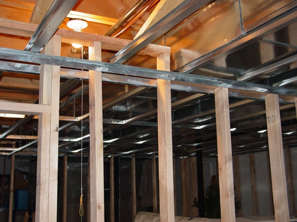
Finished Basement Edition
Doing ductwork installation sounds like a job that must be done by a professional. You may be surprised to know that by following my simple instructions, you can install your own ductwork in no time.
|
|
Installation in Pictures
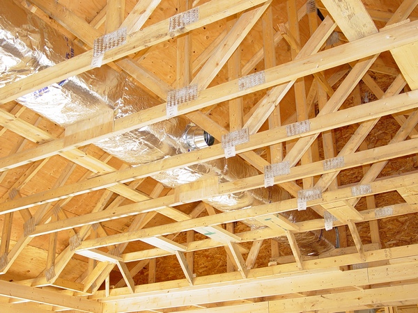
Some of the visitors of my website are very sophisticated DIY-rs. They don’t need long and detailed explanations; they just want to see how it supposed to be done so they can do it!...
|
|
Kitchen Remodeling Edition
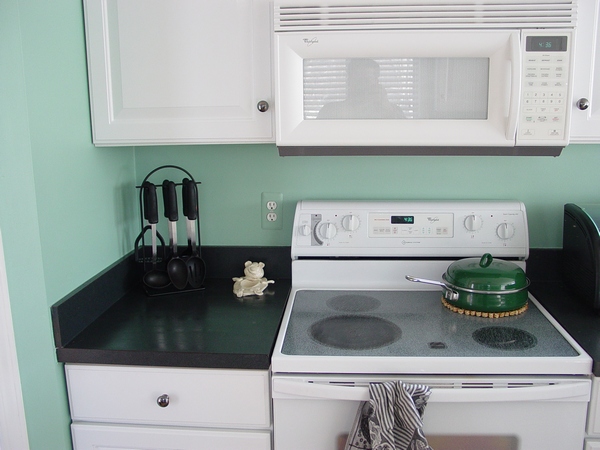
When it comes to the ductwork, kitchen remodeling requires resolving some of the most important issues, which could... |
|
Dollar Guide
This page is designed to help a homeowner with some simple issues that can arise in his/her DIY ductwork installation project.
|
|
Extending HVAC ductwork
When people are planning to change their layout of ductwork, finish a basement off, kitchen remodeling or other renovations they are usually buying my books or paid pages, because there is no other place to go. However, not all of them! Some of them are looking for help on Forum websites. Below you can see one more example of it...
|
|
Practical Ideas
Usually, when I'm not answering questions or making new pages for this website I'm monitoring numerous Forum websites. Some of the questions and solutions on these websites seem useful to me and I use them all over my website. However recently I came up with a decision to make a page where my visitors can share their ideas with me and I will publish them on this page.
|
|
Have you ever wondered what kinds of tool an ordinary residential ductwork installer carrying in his pouch?
On this and on the following pages you can see a complete set of all necessary tools that I’m usually carrying in my pouch, keeping in my toolbox or having in my van.
|
|
Ductwork Installation Tips and Tricks
Every profession has its own tips and tricks and the profession of the ductwork installer has them as well, a lot of them! On this and on the next pages I would like to introduce seventeen topics dedicated to this issue.
|
|
One Zone per Bedroom
I'd really, really like to use eight zones in the house - one zone per bedroom on the second floor, two zones on the first floor, two zones in the basement. My reasons for wanting this are:
|
|
Ductwork installer book.
I know only one and this is Ductwork Installation Guide book.
Close return vent to increase suction in another room.
Yes you can do it, but if it’s so bad I’d redesign and rebuild the entire system.
Can you use a 20x20x1 filter return air grille on a 3 ton air handler?
Yes.
How far apart do you space hangers on 14 x 12 ducts?
4’
Is it necessary to hook a return vent to a duct?
Yes.
A/C: should cold air move through furnace vent?
No, you probably have broken heat exchanger.
Assembly process for hvac ducting.
Learn how to do it in my Ductwork Installation Guide book.
Cutting a hole in the floor to get cold air out of basement.
Bad idea – cold air never rise up…
Does closing A/C register increase airflow in the others?
Yes.
Does closing air conditioning vents in rooms you don't use make the rest of the house cooler?
Yes and no at the same time. Temperature in a house depends on the thermostat setting. If you close some vents the air conditioner cycle will be shorter because the thermostat will be satisfied faster. Get more info on this page.
How to connect round duct work?
You have to crimp it first.
After how many feet do you have to reduce round metal duct work?
Usually you have to reduce round metal duct work after a take-off.
Can I use flexible exhaust venting on a high efficiency Trane Furnace?
No, must be PVC.
Formulas to get flat length of offset in sheet metal.
There is no such thing as “flat length of offset”… Learn how to calculate it on this page.
Why is air conditioning duct in Texas in the attic?
Probably, because they save money on basements…
Is it ok to have one main supply duct for main floor and basement?
Yes.
Where you find the coldest air?
In Antarctica…
Can you please fix the air vent over my head; it is very loud!
Google itself, no one can help you in this case online, please learn how to use internet wisely…
Can you lay duct work on ground where it floods?
No.
|
|
PROFESSIONALLY ANSWERED QUESTIONS
|
|
This page is designed to help people to complete their home improvement projects.
Below you can see a list of several pages every one of which is dedicated to a certain question answered before or to the one of the important stages of the project.
In order to gain accesses to any page please pay an access fee. Just click on one of the “Buy Now” button below the topic that you choose to buy. Once you pay, you will gain an instant access to the page!
Instant Access:
Register on the site first (recommended), otherwise after you have purchased a paid page; PayPal is going to bring you back to my website. In order to see the paid page you have to click on the “Register” button, fill out the form, choose your own Username and Password and click on the “Register” button at the bottom of the form – congratulation, you are now on the page you have paid for!
Important: After you have purchased any Paid page or Download page and PayPal brought you back to my website, the first thing that you should do is to save that page to your Favorites. Then if something goes wrong you always can come back to re-register yourself on my website again.
First off, I just found your site and it what a great resource! I'm finishing my basement and I've been trying to cobble together info on HVAC from all over the web, but I have found all the best info in one spot! I have purchased the cold air return and low heat instructions and should be putting them in next weekend.
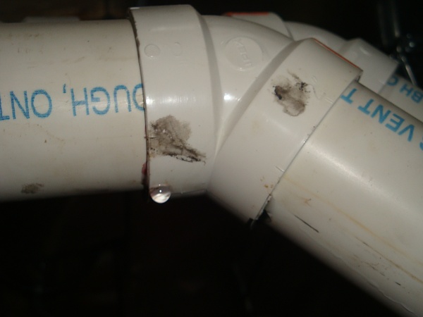
So as I was hunting around the site some more, I saw the Leaking PVC quiz. I have this EXACT same issue! I would take a picture, but it would look exactly like the one on your site. It was much worse when the heat was on in the winter, but there is still the occasional drip.
Please let me know how I can fix it, thanks!
Matt
|
|
Finished Basement Edition is e-book designed just for you! In this book you can find answers to your most frequently asked questions about ductwork installation in basement and more.
For more information please visit “Finished Basement Edition” page.
|
|
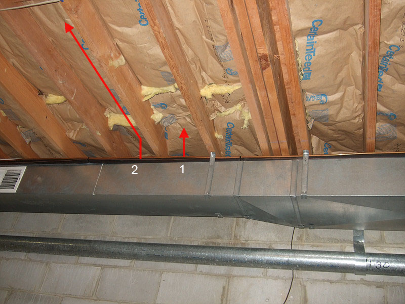
Tap Takeoff into the Existing Duct
Hello Ed,
I am installing a partition wall between the mechanical room and the semi-finished part of the basement. The semi-finished part has carpet, painted walls. But, I do not intend to install ceiling.
I want to tap into the existing duct work for air-conditioning / heating.
Since there will not be any ceiling, I could just use a round pipe and elbow to blow the incoming air from the top. For the return I need to install something in the wall yet to be built. I am not familiar with all of different types of ducting parts and tools. Therefore, I was hoping that your website could be useful.
Any help will be appreciated, even if it costs.
Thanks
If you got a similar question please click the "Buy Now" button below and get the answer.
Chapter contains 5 pictures, 3 pages. Price - $2.50.
Installation on the paid page might not exactly describe your upcoming project. However, it will give you an important example of how this type of installation should be done. In addition, it will open the gates for as many questions as necessary to make sure that the job is done right.
|
|
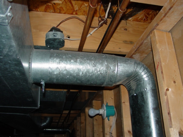
Duct Span Removal
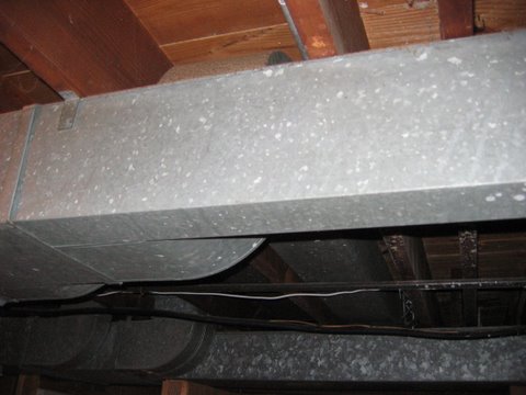
On this page you can find a detailed explanation on how to remove span of duct and how to put it back on.
This page has 12 pictures on it. Price for the instant access to the page is only $2.50.
On this page you can find the answer to this question below:
Hello, Ed!
I am doing some structural work in my basement and the only way to get in the steel is to take down a span of ductwork, or to cut it. It looks like I can take out the piece I need to, it's about 3 feet long, on one end is an elbow that turns it upstairs through the floor, and the other end joins a larger network that comes from the furnace.
I'm not afraid of home repairs, but I am a novice when it comes to HVAC. Is this something I should be able to swing on my own? If so, how do I go about removing the bands that connect the pieces, removing the piece I need to get out of the way and later reconnecting it?
Installation on the paid page might not exactly describe your upcoming project. However, it will give you an important example of how this type of installation should be done. In addition, it will open the gates for as many questions as necessary to make sure that the job is done right. |
|
Cold Air Return for Finished Basement
This chapters is a part of the Finished Basement e-book and gives a description on the installation of the cold air return on the wall which is separating the mechanical room from the rest of the finished basement. On this page, you can see pictures of all necessary tools and materials and pictures of the system elements installed. There are 40 pictures on this page. All installation is divided into six steps that represents the entire project in the making.
Installation on the paid page might not exactly describe your upcoming project. However, it will give you an important example of how this type of installation should be done. In addition, it will open the gates for as many questions as necessary to make sure that the job is done right.
This chapter contains instructions on how to cut, put together and crimp a pipe, also it include a video clip.
The price for this chapter is only $3.00.
|
|
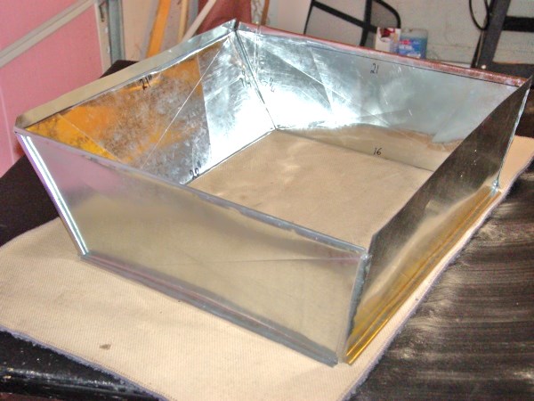
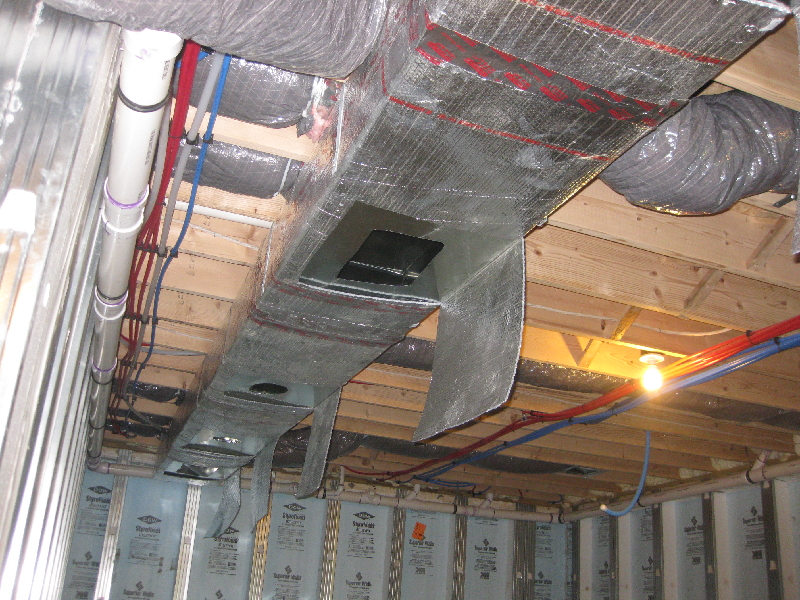
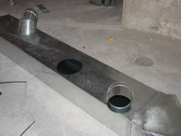
Supply Register in Basement
This page gives a description on the installation of the sleeve that is a necessary fitting designed to hold a supply register, which should be placed straight down off the main duct. On this page, you can see pictures of all necessary tools and materials and pictures of the system elements installed. There are 20 pictures on this page. All installation is divided into five steps, which represent the entire project in the making.
Installation on the paid page might not exactly describe your upcoming project. However, it will give you an important example of how this type of installation should be done. In addition, it will open the gates for as many questions as necessary to make sure that the job is done right.
|
|
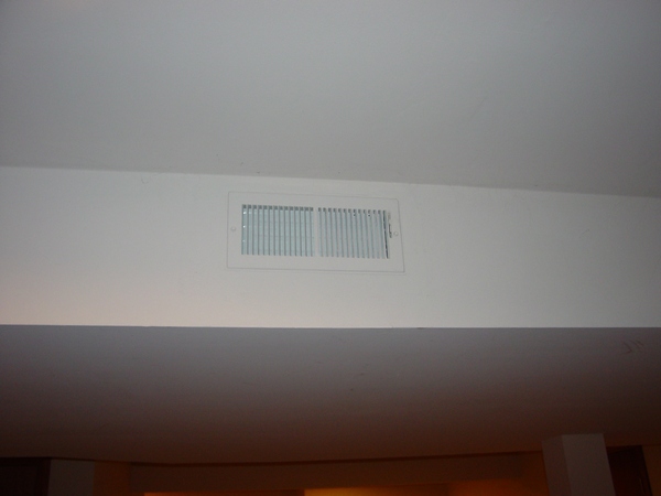
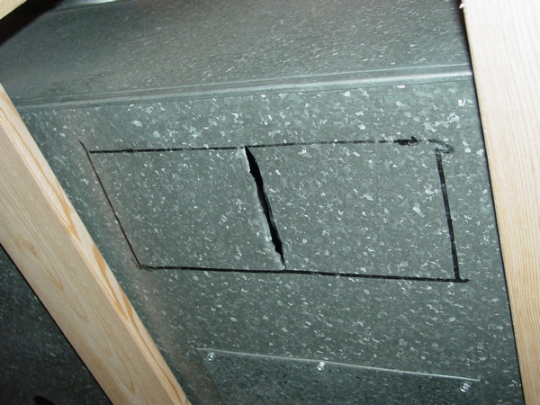
Register Installation on Ceiling Tile
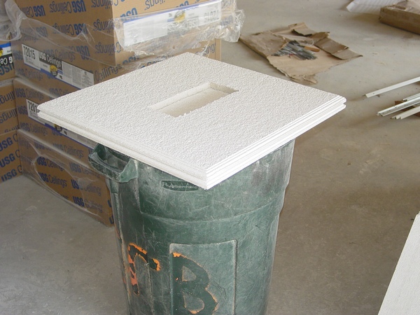
This page gives a description on the installation of a register on a ceiling tile. On this page you can see pictures of all necessary tools and materials and pictures of the system elements installed. There are 14 pictures on this page. All installation is divided into four steps which represent the entire project in the making.
Installation on the paid page might not exactly describe your upcoming project. However, it will give you an important example of how this type of installation should be done. In addition, it will open the gates for as many questions as necessary to make sure that the job is done right.
|
|
Duct Offset & Riser Formula
This page is designated to the professional visitors of my website. There you can find explanations for:
- Offset (Riser) calculation formula
- Length of a duct between two Flat or Stack 45* (30*; 60*) calculation formulas without using a center line method
- How to calculate an Offset/Riser situated between two existing ducts
- How to calculate an Offset/Riser from full length (8', 5', 4') duct and why it’s different
- How to mark a duct (ductboard) before it’s snapped together and why it’s important to do so
- How to find where hangers should be nailed
- How to find spots where Take-offs should be cut in
- What to do if the width of a duct after Offset/Riser is calculated to would be too big for connection
- How to calculate, mark out and cut duct (ductboard) in order to make a Riser and Offset (a double offset) at the same time
- How to miter shop-made Offset or Riser
- Round pipe Offset/Riser calculation without using a center line method
- Spiral duct Offset/Riser calculation between two 30* (45*, 60* elbows) without using a center line method
- How to find a minimum length for Offset/Riser
- How to figure out Offsets in ductwork without a wall
- How to Measure Degree of Offset Duct (New)
There are 24 pictures on the page. $10.00.
|
|
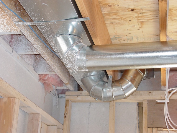
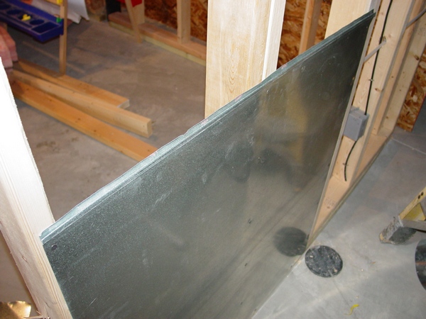
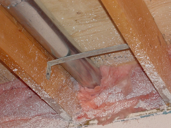
How to Extend Heat Duct to the Floor
This page gives a description on the installation of the heat duct in the wall, which separates the mechanical room from the rest of the finished basement. On this page you can see pictures of all necessary tools and materials and pictures of the system elements installed. There are 16 pictures on this page. All installation is divided into four steps which represent the entire project in the making.
Installation on the paid page might not exactly describe your upcoming project. However, it will give you an important example on how this type of installation should be done. In addition, it will open the gates for as many questions as necessary to make sure that the job is done right.
On 04/09/2016 11 pictures were added. This tutorial was extended to cover other types of interior and exterior low heat runs installations and from now on represent them all! The low price of only $2.50 will stay the same for about a month, unless I’ll see a higher demand.
|
|
Bath Fan Exhaust through Brick Wall
On this page you can find out how to run a bath fan exhaust through the brick wall. If you want to know the easiest and fastest professional way of doing that, do yourself a favor and get the information for a discount price.
On this page you can see pictures of all necessary tools and materials and pictures of the system elements installed. There are 21 picture on that page. All installation is divided into four steps that represent the entire project in the making.
Installation on the paid page might not exactly describe your upcoming project. However, it will give you an important example of how this type of installation should be done. In addition, it will open the gates for as many questions as necessary to make sure that the job is done right.
|
|
Cold Air Return from Interior Wall
This page gives a description on the installation of the cold air return from the interior wall, which separates two rooms in the finished basement. On this page you can see pictures of all necessary tools and materials and pictures of the system elements installed. There are 19 pictures on this page. All installation is divided into three steps which represent the entire project in the making.
Installation on the paid page might not exactly describe your upcoming project. However, it will give you an important example of how this type of installation should be done. In addition, it will open the gates for as many questions as necessary to make sure that the job is done right.
|
|
How to Drop a Register to Shallow Ceiling
 On this page you can find another way on how to drop a register to the soffit right below a supply duct. There are 20 (1 pic. added 01/06/11) pictures of all necessary tools and materials. All installation is divided into four steps, which represents the entire project in the making. On this page you can find another way on how to drop a register to the soffit right below a supply duct. There are 20 (1 pic. added 01/06/11) pictures of all necessary tools and materials. All installation is divided into four steps, which represents the entire project in the making.
Installation on the paid page might not exactly describe your upcoming project. However, it will give you an important example of how this type of installation should be done. In addition, it will open the gates for as many questions as necessary to make sure that the job is done right.
|
|
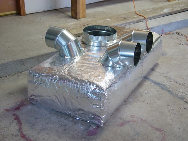
Ductwork Insulation
 Materials: Materials:
R4 Duct Wrap Insulation Sleeve Insulation
R13 Wall Insulation “Silver” Tape
Staples
Tools:
Utility Knife Tape Measure
PC4000 - Heavy-Duty PowerCrown™ Tacker Templates
Before insulating, seal all the gaps around drive, pipe connections and take-offs. The best stuff for duct seal are special mastics or duct sealants. Do not use aluminum tape – it will not stick to old ductwork because they are covered with dust..........
Installation on the paid page might not exactly describe your upcoming project. However, it will give you an important example of how this type of installation should be done. In addition, it will open the gates for as many questions as necessary to make sure that the job is done right.
Please use "Buy Now" button below, pay $2.50 and get instant access to the page!
|
|
|
A website "ductworkinstallation. com" focus on providing information and services related to the installation of ductwork systems , which are the tubes used to distribute heated or cooled air throughout a building as part of an HVAC system; essentially, it would be a platform for individuals or companies specializing in designing and installing ductwork for homes and commercial properties, offering details on the process, and potential contractors to contact for such services.
Key points about ductwork installation websites:
Services offered:
New ductwork installation, ductwork repair, duct cleaning, duct sealing, airflow balancing.
Target audience:
Homeowners looking to install a new HVAC system, individuals experiencing issues with their existing ductwork, commercial property owners needing ductwork for large buildings.
Information provided:
Explanations on different types of duct materials, design considerations for optimal airflow, potential benefits of proper ductwork installation.
|
|