|
|
|
I have a friend – an electrician, who keeps teasing me by saying that even a monkey can do this job. My answer always is - Well, of course, even a monkey can, but an electrician can't. In retaliation, I asked him several times to do some installations or at least explain the way he would be doing it, but unfortunately for him he never was successful in this regard.
As I already mentioned on some pages of this website: there is no a comprehensive nationwide “Ductwork Installation Guide” except of mine! Every company is doing the residential job by its own unique way and if you are lucky enough to be in a good company, with good traditions you may learn good ways of installation and become a good pro, if not you may end up on my “Wall of Shame” page.
From a homeowner point of view, a bad, sloppy job is going to bring only problems into the house! The problem starts up with a bad aesthetic view of the ductwork system and ends up with insufficient airflow! As one of my apprentices told me – this system of ductwork will blow air anyway! If your heating contractor will support of this kind of attitude then you, as a homeowner, are in a big trouble!
Therefore, here is a deal:
I have visitors on my website from entire country and if you, as a homeowner, are thinking that your heating contractor did a sloppy job take some pictures of the troubled spots and email them to me. Also, give me the company’s name, city and state where you are from. I will publish these photos on this page with my or yours comments to it and the country will know its heroes! In addition, I will explain how to fix it absolutely free!
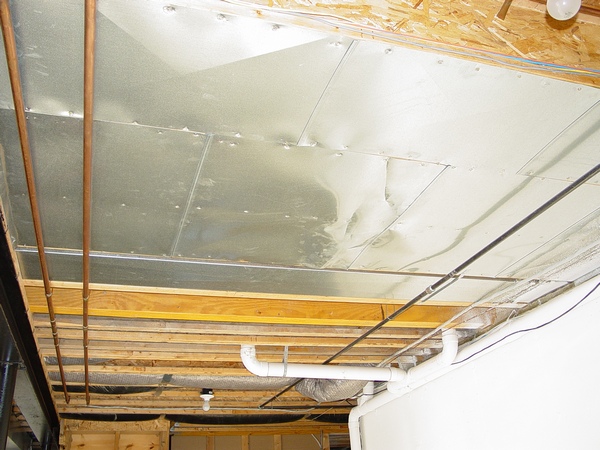
Below is an example of the very sloppy installation performed by unknown company in Farmington, MI:
The walls, which you see in the picture was built just recently, but this “jumper” in the middle of the basement was always there ! !
They made this terrible “jumper” located in the middle of the basement around the gas pipe. Besides wrong location, this “jumper” has only 90* elbows and it’s not straight!
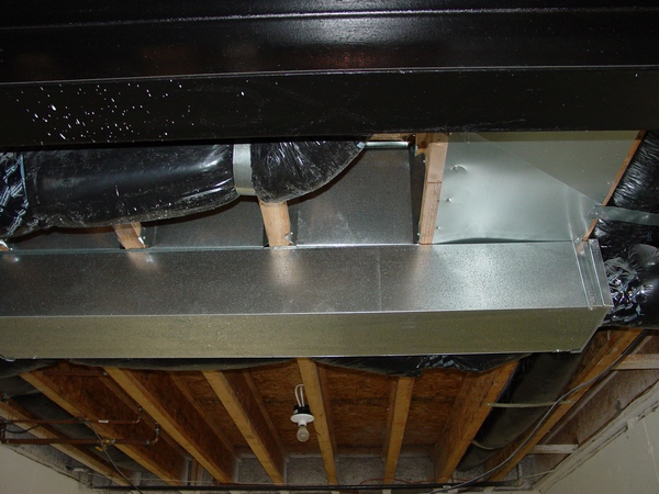
And if photos above represent relatively old installations, two photos below were taken in the new house. It's just telling us that the idiots will never die...
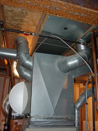
I could not believe my eyes, but this plenum with the canvas at the base is not suspended! Only drives of the starting transition are keeping it in the air. On my “Remodeling Tips” page, I already mentioned that you could not rely on the home inspector, this one probably also could not believe his eyes and passed it without any problems.
The heat run in the pictures above were done by Sun Heating and Cooling company. I don't know how they are doing now, but in the past they were famous for hiring everyone off the street and sending them without proper training right to the frontline of the new housing construction. As a result, there was a huge waist of time, materials and money.
In the pictures above, you can see just one example of that.
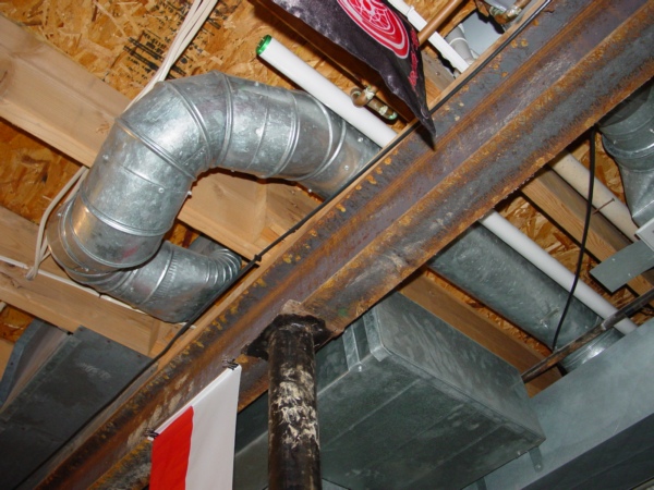
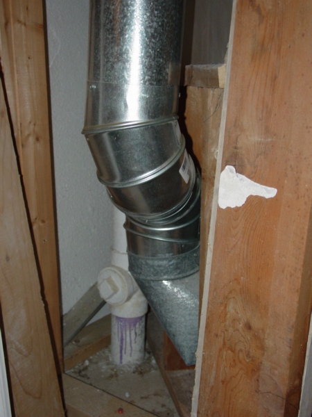
I have a question: How many elbows should the installer be using in this case?
The answer is from one to four! How many elbows the installer used - five!
Beside that, look at this installation, doesn't it look like shit?
Do you have the same kinds of BS installation in your basement? Most likely you do, it is why you are here, on this page.
Are you tired to look at it and to be embarrassed to invite your relatives and friends into your basement? Of course you are, it is why you are here, on this page.
Are you planning to fix that and make all heat runs look nice and neat? Maybe not...
However, now eventually you have a great opportunity to turn things around! Now for the very low price of only $1.86, for the price which is so low you probably won’t even bend your back to pick this money off the floor, you can buy Chapter #44 Jumper Installation from my “Ductwork Installation Guide”, or just below!
Therefore, now you will have the power to hire anyone to fix your heat runs and if he will try to screw you up again, you can read this chapter, learn how it should be done the right way, and teach him a lesson, or make him to read this chapter!
On the other hand, if you are a DIY-er you can easily do it yourself! Just follow my step-by-step instructions and fix this mess once and for all.
Submit your questions or comments here
|
|
Learn how to do a “jumper” the right way!
44. "Jumper" Installation – the chapter gives a description how to make 45 degree angle from the “elbow”.
 Chapter covers all possible cases of measurement, calculation and installation of the “jumpers”. Also the chapter covers several uncommon cases of the “jumper” installation. Chapter covers all possible cases of measurement, calculation and installation of the “jumpers”. Also the chapter covers several uncommon cases of the “jumper” installation.
The chapter has 118 pictures; 57 pages*. $2.69 (Instant Access).
On 04/26/2015 text of this chapter was significantly modified and improved. On 12/16/2016 four more pictures were added and a video file was embeded.
|
OK. Next on my list is a house in Birmingham, MI. “Kotz Heating & Air Conditioning Company” did the ductwork and furnace installation for this house. It is funny what they are writing about themselves on their website:  “Kotz Heating & Air Conditioning is considered one of the best quality dealers in Oakland County. Unlike many other companies, you can be assured that our company is fully licensed, bonded and insured. In addition, our technicians have been factory trained and tested to prove their qualifications. We use no sub-contractors; our own employees do all our work.” “Kotz Heating & Air Conditioning is considered one of the best quality dealers in Oakland County. Unlike many other companies, you can be assured that our company is fully licensed, bonded and insured. In addition, our technicians have been factory trained and tested to prove their qualifications. We use no sub-contractors; our own employees do all our work.”
By the way, several years ago I’ve contacted them by e-mail and offered that I will train an installer for them and they have to only set up an interview with him – that’s it, no obligations, no payments, but of course they, like many others, just ignored my offer!
So let’s take a look how their technicians, which “have been factory trained and tested to prove their qualifications” completely screwed up the job!
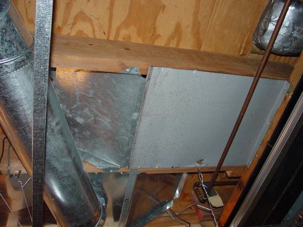 
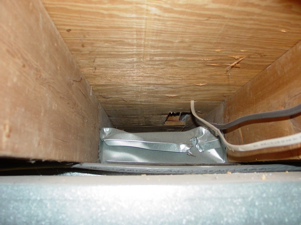
What you can see in the pictures above are installed blockers. As you can see, it has been done extremely sloppy. Through the gaps, you can easily see inside and there is enough room for a mouse to sneak-in!
Picture to the left was taken in Troy, MI. This time around, it was not a ductwork installer’s, but rather stupid electrician’s fault! A homeowner hired this knucklehead to run an additional wire and he destroyed the blocker.
Check out your basement as well, if in one of your second floor bedrooms too hot in the summertime or too cold in the wintertime then you maybe also a victim of such moronic work.
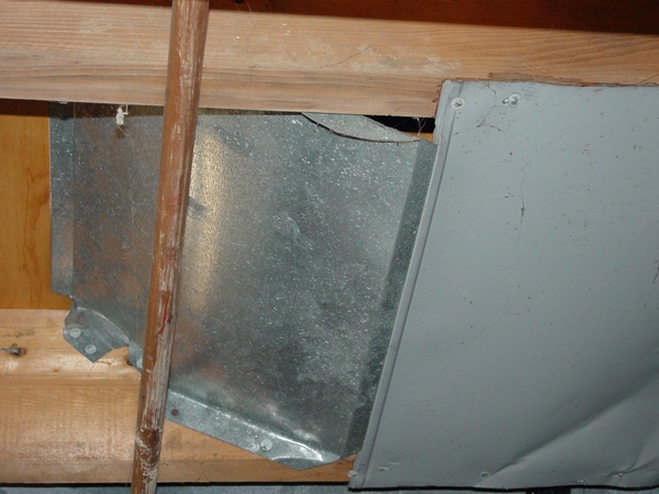
In the picture to the right, you can see another intrusion in integrality of the ductwork system. This time around, it is a plumber's fault! As you can see in the picture, this moron ran a ¼" copper pipe to the fridge and of course partially destroyed the blocker.
However, if you would like to know how to install blockers the right way you can purchase blocker installation chapters from my Ductwork Installation Guide, see them below.
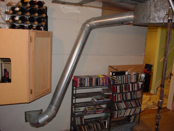
In this picture on the left, you can 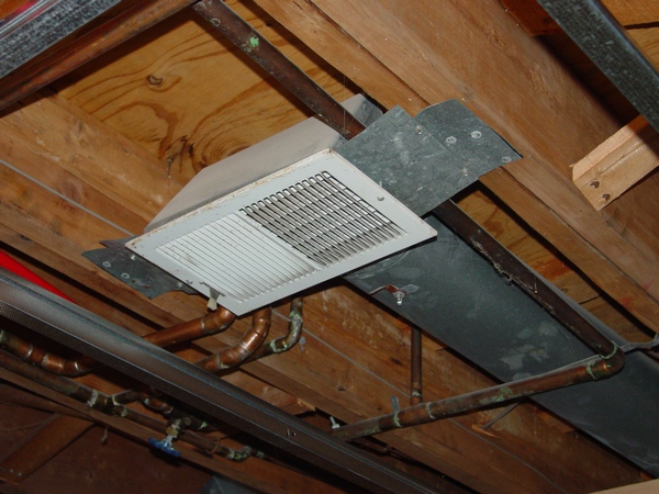
see a basement heat. This monster is hanging down way below the joists level and looks like s--t. Of course, I understand this is just a basement, the place where people stock their garbage. However, I would not respect myself if I would be doing work like this!
If you would like to know how to install the basement heat the right way you can purchase Basemen Heat chapter from my Ductwork Installation Guide, see it below.
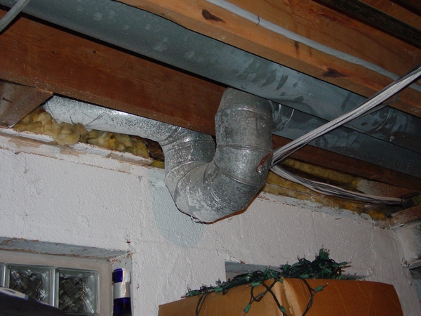 

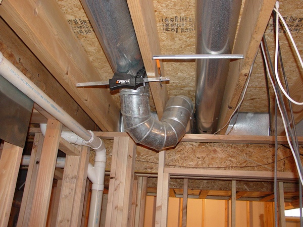
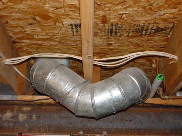
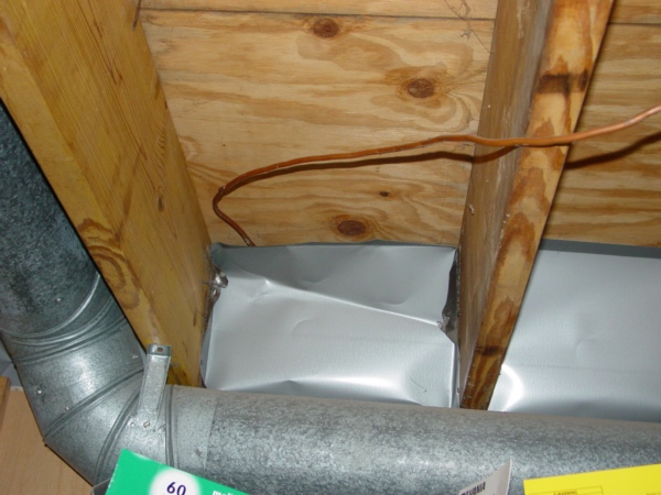
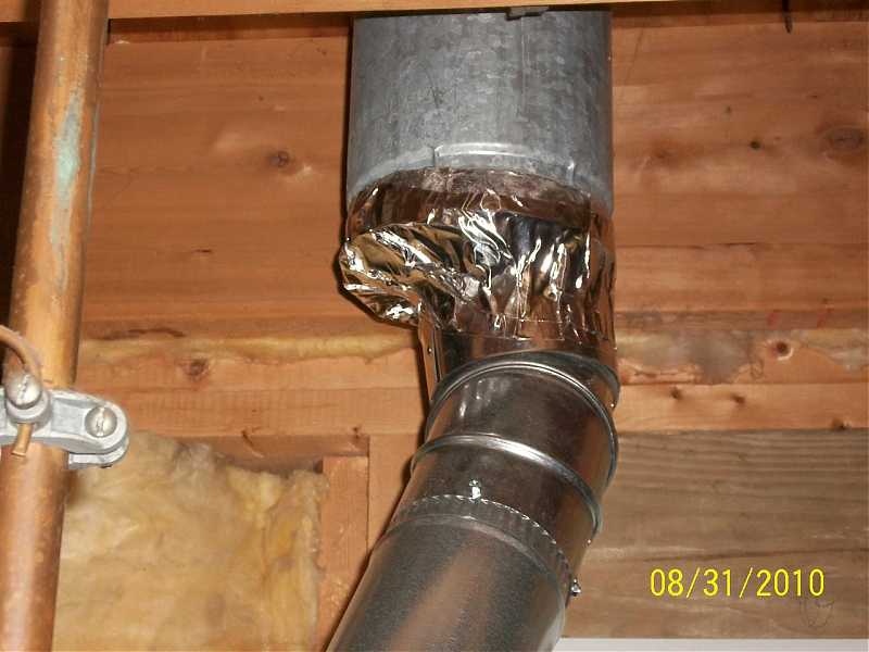
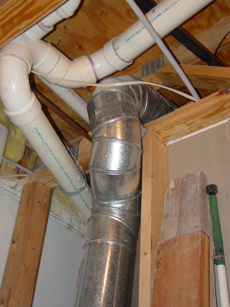
Moreover, here are two jumpers again! It is very difficult to understand how “factory trained and tested to prove their qualifications” technicians could have made this kind of sloppy job!
What you can see in the first picture to the left proves that there was no conducted tests, but maybe only test on the level of stupidity! Everyone in this business of ductwork installation knows that every elbow has its resistance to the airflow. Resistance of one 90* equals 10’ of pipe, so those "factory trained technicians” put in one spot Oval 90*, From Round to Oval 90* and four elbows! As a result, they made resistance equal 60' of pipes!!! (Factory trained my ass). But if there would be Ed’s trained and tested tech he would’ve installed one Oval, two Round 45*-s and one elbow equal 25’ of resistance – as a result more than twice less resistance!
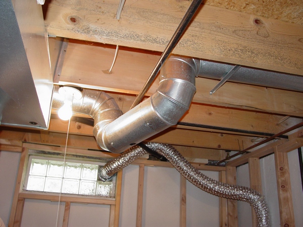
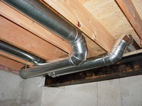
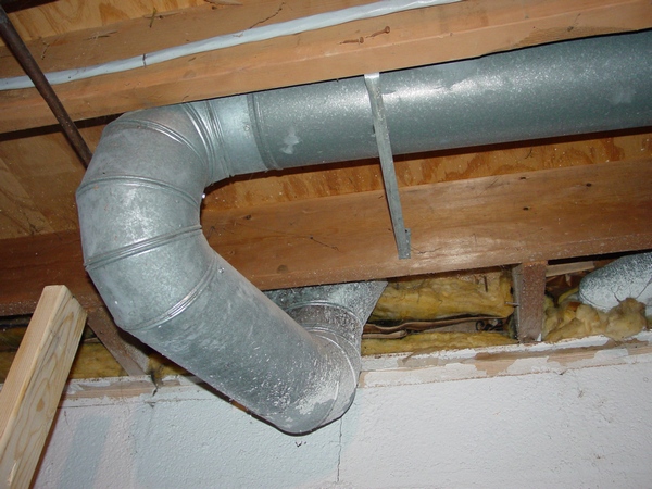
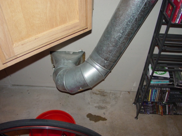
On the second picture, you can see ONLY two mistakes:
1. Instead of the Round 90* they should’ve use Round 45*!
2. "Factory trained technicians" who were doing this job were in a hurry or maybe couldn’t do the job right due to the extensive training, but he used a full piece of 6” pipe, so the pipe passed its goal and he ran a jumper back to the straight boot!
 Therefore, if you live in Oakland county MI you can hire this “infamous” company and your basement will looks like one in the pictures above! Therefore, if you live in Oakland county MI you can hire this “infamous” company and your basement will looks like one in the pictures above!
I'm in the midst of resolving issues with my builder over the installation of a new split system that is specs out to be Goodman/16 Seer. I'm not a DIY, just a homeowner trying to get smarter on what is considered to be a "proper installation". Any advice or comments on the installation would be appreciated.
What about plenums for the air handler connections to supply and return?
Thanks!
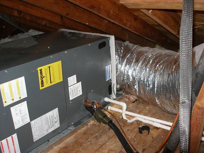 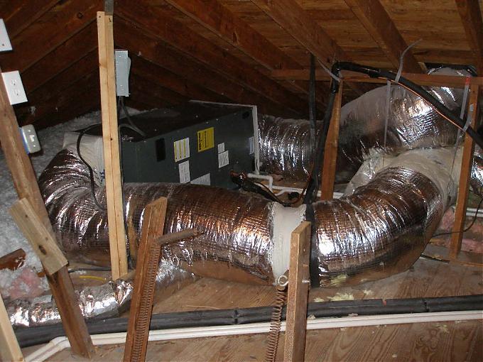
The supply and return "plenums" are non-existent, likely causing high static and low air flow. I'd want the ESP (external static pressure, think resistance to airflow) of the duct system tested.
And it also crushed one of those ducts to about half capacity.
I can not for the life of me understand why contractors don't get air handlers higher off of drain pans so there is plenty of room to put in proper condensate traps and be easier to work on. And they could just cut the trap shorter instead of cutting the deck. Also, not having even a two foot section of supply or return plenum is just asking for unnecessary problems.
In the photo to the right they used band iron to hang the flex and the line set! It’s also wrong! Over time the band iron will cut through the flex. And the same fate, expect the copper touching the steel!
In the first picture they centralized cold air return plus two more connected to the box, it may not works because it’s easier for air come through the grill then through small size smashed flexes.
In all the pictures you can see wrong flex connections: no insulation and unnecessary use of sealing mastic which in this case absolutely useless!
If you would like to learn about proper installation of the Air Handler you can purchase Air Handler Installation chapter from my Ductwork Installation Guide, see it below.
Submit your questions or comments here
|
|
Learn how to install a blocker the right way!
21. Blocker Installation* – the chapter gives general information about blockers and after that gives detail 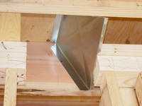 explanation of all possible cases of their installations. explanation of all possible cases of their installations.
The chapter has 16 pictures; 11 pages*. $2.00 (Instant Access).
*Article:
Thermo-pan Installation Instructions.
On 03/28/2015 text of this chapter was significantly modified and improved. On 08/16/2015 one bmore picture was added.
|
|
Learn how to install an air handler the right way!
56. Air Handler Installation*# – the chapter provides examples of air handler installation in the attic and describes ductwork installation techniques for existing houses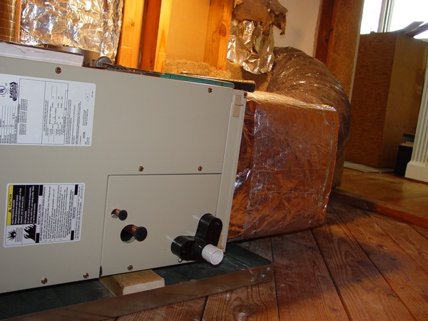 . The chapter has 23 pictures; 7 pages*. $2.50 (Instant Access). . The chapter has 23 pictures; 7 pages*. $2.50 (Instant Access).
PDF files:
Air handler Installation Manual.
Proper Subcooling Charging Techniques.
#From code:
M1305.1.3 Appliances in attics.
On 03/18/2015 text of this chapter was significantly modified and improved. Link to the International Code added (01/18/2012).
|
|
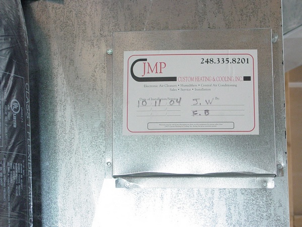
OK, another day, another basement and of course another shameless installation performed by another shameless company!
This time around it is JMP Custom Heating & Cooling, Inc!
 You know, what is funny about this company it’s that I already tried to deal with this company’s sloppy work in the past. It happened about eight years ago. I was helping a homeowner in his project of finishing his basement off and I encountered multiple mishaps in the ductwork installation done by this company’s employees. You know, what is funny about this company it’s that I already tried to deal with this company’s sloppy work in the past. It happened about eight years ago. I was helping a homeowner in his project of finishing his basement off and I encountered multiple mishaps in the ductwork installation done by this company’s employees.
At this time the homeowner had a vacation which he used to finish his basement by himself and every time he came down in the basement I’ve met him with a new revelation. We were laughing all day long, but for him it actually wasn’t a laughing matter because after all it was his basement and it was his heating system!
Of course I don’t remember everything, but, for example I remember that the main duct had a turn for 90* to be run above the I-beam and instead of running it up, at first, they ran it down, way below the I-beam!
Also, among the other mistakes, there was a terrible ticking noise coming from the entire ductwork!
This house was actually part of the large subdivision of about 50 or so houses in Novi, MI and I was naïf enough to think that I had a great opportunity to earn some money! I came to a conclusion that if the same heating company has been involved in the entire subdivision the way they were involved in that house – there should be a lot of problems in the other houses as well!
So, I made 50 or so fliers and in a sunny Saturday’s day put them in every mailbox. There were a lot of people who obviously saw my marked with the company’s name on my truck; they saw me putting fliers in the mailboxes, but nobody even bothered to respond!
I knew there was terrible installation in every house, I knew there were loud and annoying ticking noises and it was zero calls on my phone! Anyone can explain why? If you have any explanations you can type them here. If you have any explanations you can type them here.
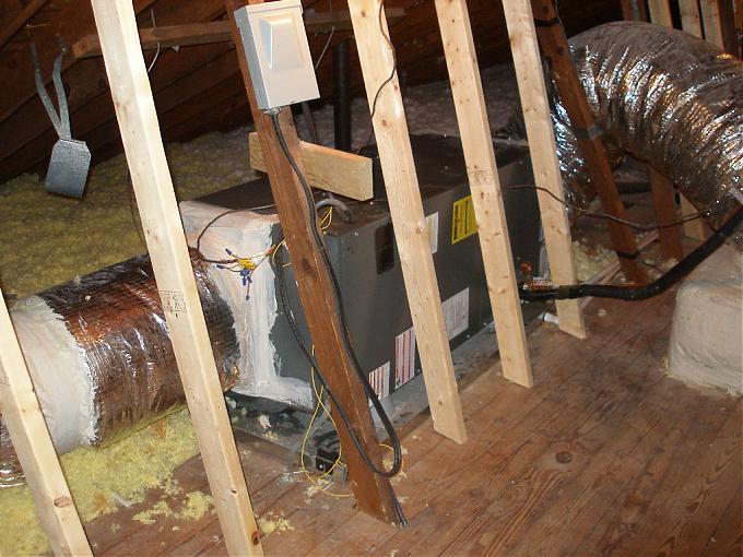
Ok, let’s come back to the house in Northville, MI. What you can see in this picture is an 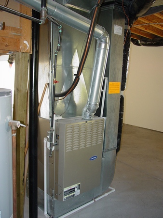 80% eff. furnace with an exhaust pipe way off the plumb! Its looks like that an installer was pretty much drunk and didn’t understand what was going on with this installation! As much as he didn’t understand that he should put a piece of pipe with a cap on that tee before the condensate trap! 80% eff. furnace with an exhaust pipe way off the plumb! Its looks like that an installer was pretty much drunk and didn’t understand what was going on with this installation! As much as he didn’t understand that he should put a piece of pipe with a cap on that tee before the condensate trap!
The reason why it’s necessary to put a trap for this kind of application in the first place is to prevent conditioned air from escaping into the basement through the condensate pipe and the tee without cap pretty much undermine this notion.
In this picture you can see double sheeting nailed to the studs. Its looks like that before installation and that team of hacks were dancing on it for at least an hour!
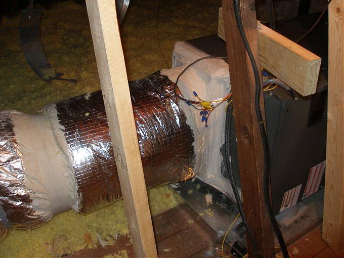
In this picture you can see big gaps between the duct and the other system elements.
Here I would like to bring a little bit more of your attention.
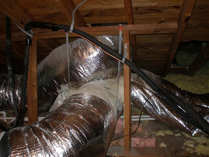
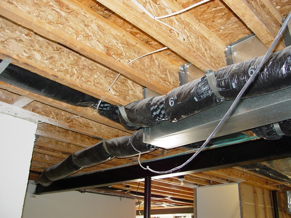
They ran all the heat runs in insulated flex and you can see how that flex was choked by the hangers!
Someone may say that it’s not a big deal! Down South they are installing all systems in flex, but in my opinion this kind of installation is a crime! I keep seeing on the forum websites people complaining about high electrical bills and I believe they have it because of this kind of installation! Putting heating and cooling duct in the attic space where temperature can reach 120 – 150 degrees is a no-brainer!
Someone can also say that here on this website you have a page were you are showing how you installing the system in the attic! Well it’s true! But it’s a homeowner's decision. He is a millionaire and he obviously doesn't care how much his electrical and gas bill will be! He already has four HVAC systems in his house and I’m in the process of installing of three more! But in his particular case I’m running all the ductwork as low as possible, because I want to bury it under the blow-in insulation. If down south every homeowner is also a millionaire then I’m sorry for my remarks!
Submit your questions or comments here
|
|
Chimney liner
This install was giving me and my client headaches from CO spillage.
After seeing the poorly sealed cap at the chimney, then the improper connected pipe at the water heater/chimney followed by the wye fitting not in use and improperly sealed.
I then open the chimney cleanout and looked up and noticed the liner. I figured since the water heater flue was loose I would pull out.
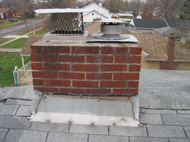 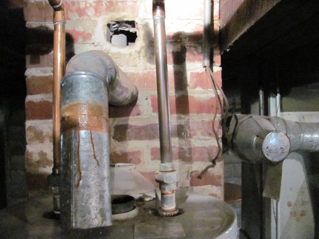
 They ran the water heater exhaust into a sealed flue!? They ran the water heater exhaust into a sealed flue!?
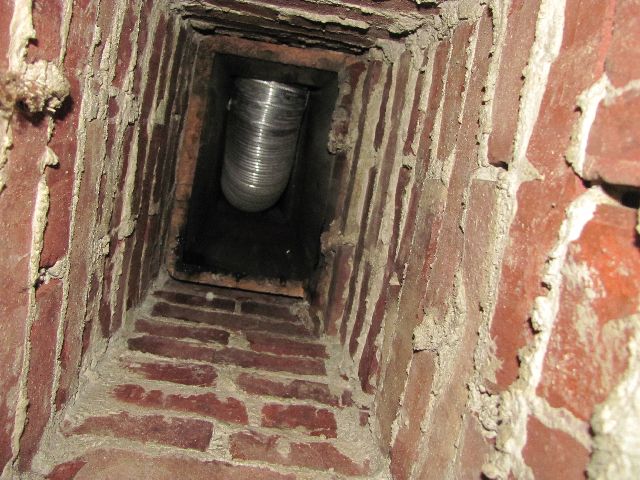
Here is a pic of the metal liner as viewed thru the clean out door by the mechanical systems. Water heater flue not connected.
Patrick J. Cloninger
InterNACHI Member Home Inspector TN
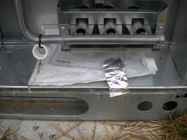 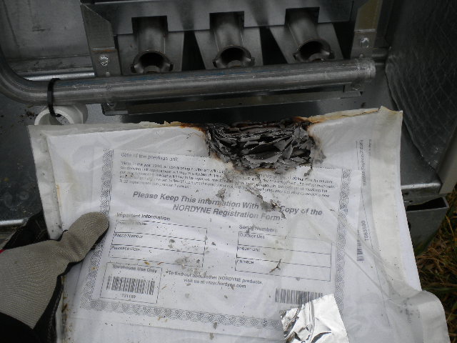
This is something I've been seeing too often in new homes. HVAC installers are putting the operating manual/warranty inside the burner cabinet.
This was from a couple of days ago on a new home.
 "On a recent inspection, I came across this. A new HE furnace was installed but they kept the hot water heater on the old vent. This vent goes through the roof. I don't mind the vent size but duct tape as a connector. I have searched the threads and since my codes books were "removed from my premises", stolen, I haven't confirmed this is incorrect. The installation was by a very large firm in our area and I certainly don't want to call it unless I have some back up. Can anyone shed some light on this for me?" "On a recent inspection, I came across this. A new HE furnace was installed but they kept the hot water heater on the old vent. This vent goes through the roof. I don't mind the vent size but duct tape as a connector. I have searched the threads and since my codes books were "removed from my premises", stolen, I haven't confirmed this is incorrect. The installation was by a very large firm in our area and I certainly don't want to call it unless I have some back up. Can anyone shed some light on this for me?"
So, what we can learn from this post:
First off, those installers from a "very large firm" do not care what they were doing, while completely hacking this job!
And secondly, an inspector is just an uneducated dumbass who doesn't know shit about ductwork installation! Such a disgrace!
Submit your questions or comments here
|
|
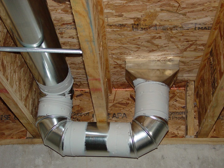
Hacks from the unknown company definitely didn't know how to do a low heat for the finished basement!
First off, they used wrong fitting as a register box, which brought everything far away from the wall.
Secondly, once they realized that they used two elbows to direct it to the wall, stopped on the halfway and ran it aslant to the curved side of the flat 90*!
Therefore, just in one installation they've made five stupid mistakes!
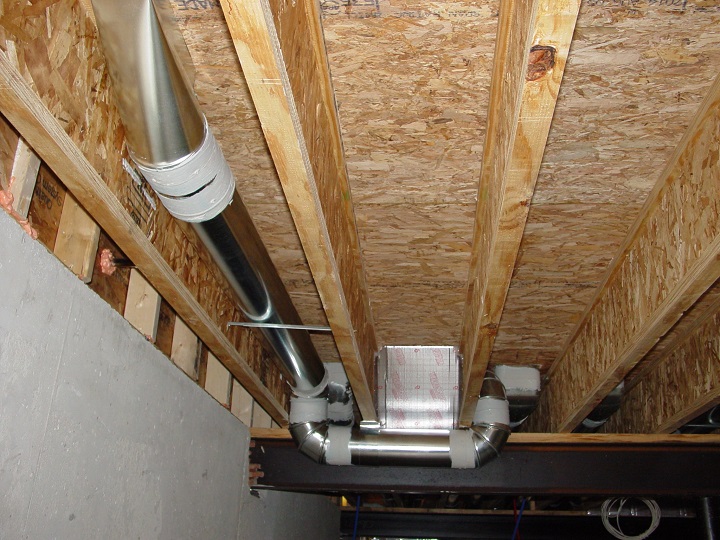
  And here is another ugly installation! The installer used only five elbows, but who knows maybe before he use to work in Serpent Safari... And here is another ugly installation! The installer used only five elbows, but who knows maybe before he use to work in Serpent Safari...
Submit your questions or comments here
|
|
|
A website "ductworkinstallation. com" focus on providing information and services related to the installation of ductwork systems , which are the tubes used to distribute heated or cooled air throughout a building as part of an HVAC system; essentially, it would be a platform for individuals or companies specializing in designing and installing ductwork for homes and commercial properties, offering details on the process, and potential contractors to contact for such services.
Key points about ductwork installation websites:
Services offered:
New ductwork installation, ductwork repair, duct cleaning, duct sealing, airflow balancing.
Target audience:
Homeowners looking to install a new HVAC system, individuals experiencing issues with their existing ductwork, commercial property owners needing ductwork for large buildings.
Information provided:
Explanations on different types of duct materials, design considerations for optimal airflow, potential benefits of proper ductwork installation.
|
|