Kitchen Ideas That Work
Book Description
Publication Date: January 1, 2007 The home you've always dreamed of starts here! Kitchen Ideas that Work combines fresh ideas with professional design advice so you can create the kitchen you've always wanted. No other book on the market offers this much useful information and fresh inspiration for less than $20.
Kitchens are more than where we cook a meal and wash dishes. It's where our day begins and ends, where family gathers for conversation, homework, and snacks, and where we entertain friends. With the prominence of this space in both our homes and our lives it's no wonder that kitchen remodeling is the number one home improvement project. Kitchen designer Beth Veillette provides professional design advice for kitchens and budgets from small to large. Throughout the book she offers design options for all components found in the kitchen as well as how to successfully combine them to create a great kitchen. A wide range of styles, materials, and layouts are featured in hundreds of photos that provide fresh ideas for everything from the floor material to wall color, lighting to seating, and appliances to window treatments.
Highlights include:
Essentials: Providing comparison information on all elements in the kitchen to help you make smart buying decisions
Putting it All Together: Case studies focusing on creative ways to combine elements to create a kitchen that works
Details that Work: Spotlights neat details that personalize the space
Design Gallery: Design options for everything from sinks and faucets to window treatments and bar stools.
Customer Review
This is a great book! It has tips, and design ideas for all tastes. It covers everything from trim, islands, stoves, floors, sinks, backsplash, basically everything and a lot of custom ideas too. |
Lyn Peterson's Real Life Kitchens
Book Description
Publication Date: November 6, 2007
More than just a place to cook, the kitchen has become the heart and hub of the home. It’s where we entertain friends, spend time with family, and indulge in a moment alone. The modern kitchen has to be equipped for working, studying, socializing, and hanging out; it should be functional without sacrificing an ounce of style or comfort. Now, homeowners are putting more of themselves into the kitchens they renovate or build, working to create spaces that reflect their personalities and complement the way they live. In Lyn Peterson’s Real Life Kitchens, the acclaimed designer and decorator tells you everything you need to know to transform your kitchen.
This practical book is packed with cutting-edge ideas and information, from the latest options for appliances, countertops, and cabinetry to advances in seating, lighting, flooring, and kitchen configurations. Lyn Peterson’s Real Life Kitchens takes you step-by-step through the decisions you’ll need to make on all of the most important functional and stylish elements.
The Big Picture: Deciding when and why to update, knowing how to optimize your space, nailing down a budget, and learning from the shortcomings of your previous kitchen
The Layout: Thinking outside the traditional kitchen triangle, matching an island to traffic flow, and putting your plan to paper
The Appliances: From cooktops to warming drawers, dishwashers to refrigerators, the latest advances and options in all of the working elements
The Cabinetry: Choosing between ready-made, semi-custom, and custom; judging quality construction; saving money on this most expensive element of your renovation
The Surfaces: Floors, countertops, and backsplashes, from painted to pine, tile to granite to limestone—the choices seem endless, but here’s how to match your budget to the style you want
The Lighting: The looks, the lingo, and the low down on task, natural, ambient, accent, and mood lighting
The Auxiliary Spaces: Pantry and storage options, wine cabinets and cellars, mudrooms, and a “desklet” for kitchen office activities like checking e-mail and scheduling
A Survival Guide: Must-have information for working with contractors, designers, and architects, as well as creating a substitute kitchen while yours is under construction
The Resources: A host of all-important sources to help you start your search
Sprinkled with enlightening recollections from families who are veterans of both high-end and budget-conscious renovations, and packed with no-fuss advice for getting the most out of your space and your budget, Lyn Peterson’s Real Life Kitchens is the key to achieving your dream kitchen.
Customer Review
This book is like a secret interior designer’s handbook for all to understand. It answers all questions and gives opinions of the author's own personal style as well as her clients. She projects actual dimensions (such as how much countertop overhang is needed at the kitchen island for a stool) so you know what you are talking about when you meet with the designers that you are going to purchase goods from. I have found this book much more helpful than all the other kitchen books I have combined. Well worth the money. |
Illustrated Cabinetmaking: How to Design and Construct Furniture That Works
Book Description
Publication Date: April 1, 2008
Featuring each piece in highly-detailed, exploded drawings and applying time-honored dimension and ergonomic standards, this comprehensive visual sourcebook takes the guesswork out of furniture joinery, assembly, dimension, and style. Woodworkers of any skill level will benefit from more than 1,300 crisp and detailed drawings that explain classic solutions to age-old problems, such as hanging a drawer, attaching a tabletop, and pegging a mortise. Covering hundreds of pieces of furniture, including kitchen cabinets, dining tables, desks, bookcases, and chests, readers will unlock the mysteries of legs, moldings, separate braces, and dozens of other subassemblies. Customer Review
I like to check out books from the library before I buy them. I checked this one out, now I'm buying it. As a novice woodworker, I anticipate this will be an excellent reference as I move forward with designing and building cabinets, tables, and chairs. It's not a how-to book, it's a reference. So when I'm wondering how I'm going to design a small cabinet with four drawers and a television cabinet for the bedroom, this book will give me options and ideas from casework to drawers to what goes on the bottom and what goes on the top. |
|
Kitchen Remodeling Edition
|
|
When it comes to the ductwork, kitchen remodeling requires resolving some of the most important issues, which could arise during the remodeling process.
For example:
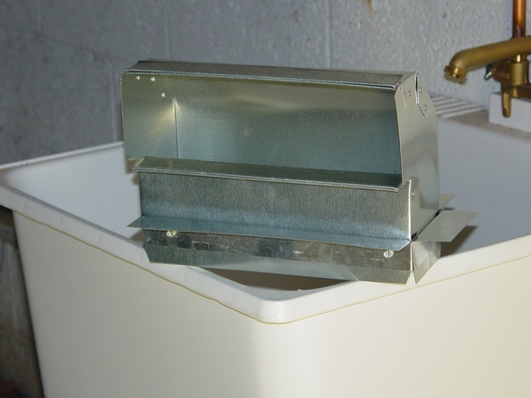
- Bathbox installation/relocation
- High wall heat installation
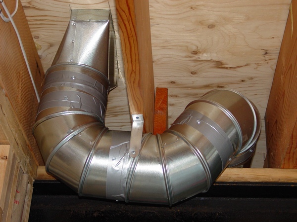
- Toe kick heat installation
If in your kitchen you are doing a remodeling project on moving a wall, you may find out that existing heat no longer can serve your kitchen area and should be moved to another location. It is why I give you three options of resolving this issue:
If you have an unoccupied span of wall you can install a bath box in, if not, you can install a bath box high above your wall cabinets, or you can set it low and bring such necessary heat to your kitchen area as the Toe Kick heat.
Next and the most important part of your kitchen-remodeling project is a kitchen exhaust. Here you can also have three options:
- Microwave Hood exhaust
- Kitchen Hood exhaust
- Downdraft Range exhaust
All three of them require resolving of some ductwork installation issues and you are able to find the solutions in my book.
The “Jumper Installation” chapter of my book gives you insight on how to run heat or exhaust if you unable to run it as a “straight shot”.
All the chapters are very cheap and the book price is even cheaper than combine the price of all chapters. However, you may be worried that there is no answer to your particular question or issue, and then you have two options:
- You can buy the book and if you are unable to find an answer to your particular question I will answer it free of charge
- You can ask your question before the book purchasing and I will tell you if there is an answer in the book. You can type your question here.
Chapters of the book:
- Bath Box Installation
- High Wall Heat Installation
- Toe Kick Heat Installation
- "Jumper" Installation
- Kitchen Exhaust
- Tools and Materials
What is a Range Hood
Instant Access:
After you have purchased a paid page; PayPal is going to bring you back to my website. In order to see the paid page you have to click on the “Register” button, fill out the form, choose your own Username and Password and click on the “Register” button at the bottom of the form – congratulation, you are now on the page you have paid for!
Important: After you have purchased any Paid page or Download page and PayPal brought you back to my website, the first thing that you should do is to save that page to your Favorites. Then if something goes wrong you always can come back to re-register yourself on my website again.
|
|
1. Toe Kick Heat Installation – the chapter covers several topics and gives explanations:
- How to make openings in the floor and in the cabinet
- What kind of fitting should be used
- How to cut a take-off in
- How to run a pipe
- How to terminate a heat run
The chapter could be useful for the kitchen or bathroom remodeling project or to any project alike. The chapter has five pages, 10 pictures. $2.50. (Instant Access).
|
|
2. High Wall Heat – the chapter covers several topics and gives explanations:
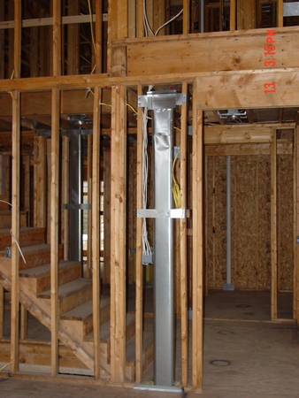
- How to install High Wall Heat and what kind of fitting should be used
- How to measure, cut, and put together piece of oval stack or pipe
The chapter could be useful for the kitchen or bathroom remodeling projects or to any project alike. The chapter has four pages, two pictures in it. Price of the chapter is only $2.50 (Instant Access).
|
|
3. “JUMPER” INSTALLATION – the chapter gives explanations:
- How to run a “jumper” to the Toe Kick 90*
- How to run a “jumper” to the Oval Stack
The chapter could be useful for the kitchen or bathroom remodeling projects or to any project alike. The chapter has nine pages, twenty pictures in it. Price of the chapter is only $2.50 (Instant Access) |
|
4. MICROWAVE HOOD, JENN AIR, KITCHEN HOOD
 the chapter describes all three cases of the kitchen exhausts: Kitchen Hood, Microwave Oven Hood, Jenn-Air Fan; explains the roof and wall caps installation; covers the ductwork installation. Chapter has 10 pages, 30 pictures. Price of the chapter is only $3.59 (Instant Access). the chapter describes all three cases of the kitchen exhausts: Kitchen Hood, Microwave Oven Hood, Jenn-Air Fan; explains the roof and wall caps installation; covers the ductwork installation. Chapter has 10 pages, 30 pictures. Price of the chapter is only $3.59 (Instant Access).
This discussion took place on the forum.doityourself.com website:
Question
I have a GE JV966DSS that calls for 7" ducting. It is rated at 600 CFM with two fans installed 30" over a 36" GE gas cook top with 5 burners. Well, the HVAC person came when I wasn't home, and installed 6" ducting instead, about 30" of it through the roof. Poor communication on my part. Should I call him back to install 7" instead? How much effectiveness did I reduce by going with 6" vs. 7"? Thank you in advance.
Answer
With 600 CFM I think 7” would be too small. I think an eight inch would be better so the static pressure is not off the chart. But I would add that I would go with what the manufacture recommend. Make sure you seal the duct because it will push any grease out the seams at that kind of pressure.
Feedback
Thanks. Well, I called the HVAC Company. They said they don't install 7" ducting. They have 8" ducting, but only install them if the hood calls for 8". He said 6" shouldn't reduce the efficiency too much. I don't agree with him as it stated clearly in the manual that going smaller will decrease the efficiency. A 15% decrease in diameter will reduce the flow by almost 50%, the equivalent of doubling the length of the pipe I suppose. With the length of my pipe at 45’, it effectively increases it to 90’, technically still below the 100 ft maximum length per manufacturer recommended. I am not happy, but they are not going to install either 7" or 8".
That’s it! But what that homeowner could do, I think you already got the answer! Of course if he would purchase the MICROWAVE HOOD, JENN AIR, KITCHEN HOOD chapter then:
- He could do it himself
- He would know how this installation should be done and hire someone
- He could ask me some questions before this started and after it’s done
I know I know the price of any home improvement project easily adds up, and even $3.59 for this chapter seems too high when you already spent hundreds of dollars on everything else. It is true, but what this guy is going to do now… have the answer?
|
5. BathBox Installation – the chapter covers bathbox installation in the interior wall. The chapter 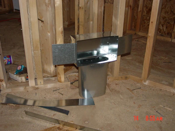 could be useful for the kitchen or bathroom remodeling projects or to any project alike. The chapter has two pages, one picture in it. Price of the chapter is only $1.49 (Instant Access). could be useful for the kitchen or bathroom remodeling projects or to any project alike. The chapter has two pages, one picture in it. Price of the chapter is only $1.49 (Instant Access). |
|
Range Hood in Finished Basement Installation in Pictures
On the rare occasion, people who finish their basements off put an additional kitchen. This kitchen as any other may have a microwave hood or kitchen hood and on this page you can learn how to install it.
On this page, you can see illustrations of all installation in the making except installation of the kitchen hood itself. However, if you would purchase this page by the time you will be ready to mount one I will make all necessary additional pictures and invite you back to this page.
On the page, you can see 20 pictures of the tools and materials and 9 pictures of installation that represent it in the step-by-step manner.
In order to gain an accesses to the Finished Basement Kitchen Hood (Installation in Pictures) page you have to pay an access fee of $1.34. Just click on the “Buy Now” button below. Once you pay, you will gain an instant access to the page!
Instant Access:
After you have purchased a paid page; PayPal is going to bring you back to my website. In order to see the paid page you have to click on the “Register” button, fill out the form, choose your own Username and Password and click on the “Register” button at the bottom of the form – congratulation, you are now on the page you have paid for!
Important: After you have purchased any Paid page or Download page and PayPal brought you back to my website, the first thing that you should do is to save that page to your Favorites. Then if something goes wrong you always can come back to re-register yourself on my website again.
|
|
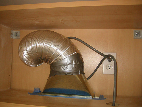
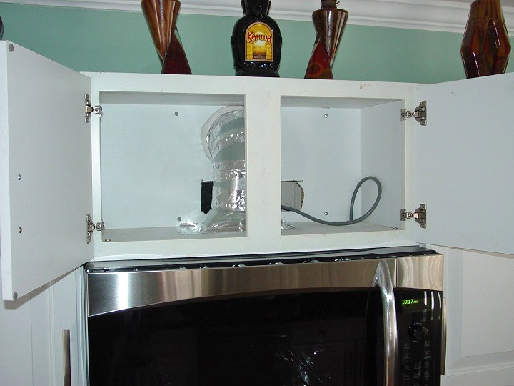
Microwave Hood Vent Installation in Pictures
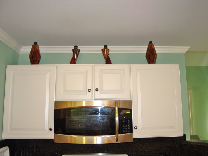 A microwave that you can see in the picture on the left top corner was working in the recirculation mode. Unfortunately it didn't serve the purpose and idea to exhaust it to the outside eventually came to fruition! A microwave that you can see in the picture on the left top corner was working in the recirculation mode. Unfortunately it didn't serve the purpose and idea to exhaust it to the outside eventually came to fruition!
The most discouraging part of this project was microwave's location - it was sitting on the interior wall and of course you would never know what kind of obstacles you may encounter on the way through the stud and joist cavities!
However everything were resolved successfully, all obstacles were overcome and this microwave hood was vented the way you can see it in the picture on the left bottom!
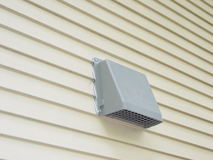
So, here you can see only two pictures - before and after, but what about the other 53 of them that were taken during installation process? No problem, for the price of only $2.50 you can see them all. Just click on the Buy Now button below and get an instant access to 55 high quality pictures with brief explanations to them!
|
|
How to Hook up Kitchen Hood in Remodeling Project Installation in Pictures
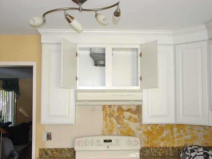 On this page you can find a step-by-step guidance that include 9 high quality pictures with brief explanations. The price of this page is only $1.34. On this page you can find a step-by-step guidance that include 9 high quality pictures with brief explanations. The price of this page is only $1.34. |
|
Microwave Exhaust for Small Cabinets
If you have small cabinets there might be not enough room for the factory supplied damper or/and the collar can be off-center and you also cannot use 10" x 4" 6" straight boot and 6" elbow. In this case you have to do something else!
So, for the price of only $2.50 you can learn what should be done. This paid page has 25 high quality pictures with brief explanations.
|
List of YouTube Videos
01. How to Install New Panasonic NN-SD277WR Microwave
02. Improperly Installed Microwave Found by Madison MS Home Inspector
03. Replacing Microwave Wave Guide Cover
04. Microwave Fixing
05. Range Hood Installation
06. Kitchen Cabinet Installation
07. Vent-A-Hood Introduces Duct-Free ARS Hoods
08. Vent-A-Hood Company History
09. Vent-A-Hood University
10. Kitchen Equipment: The Range Hood
11. Veneto European Range Hood Wall Mount B2W
12. PLZW Range Hood Install Slide Show
13. Do It Yourself Kitchen Installation - Part I
14. Do It Yourself Kitchen Installation Part II
15. Do It Yourself Kitchen Install Part III
16. Range Hood, To Circulate or Not Circulate |
|
|
A website "ductworkinstallation. com" focus on providing information and services related to the installation of ductwork systems , which are the tubes used to distribute heated or cooled air throughout a building as part of an HVAC system; essentially, it would be a platform for individuals or companies specializing in designing and installing ductwork for homes and commercial properties, offering details on the process, and potential contractors to contact for such services.
Key points about ductwork installation websites:
Services offered:
New ductwork installation, ductwork repair, duct cleaning, duct sealing, airflow balancing.
Target audience:
Homeowners looking to install a new HVAC system, individuals experiencing issues with their existing ductwork, commercial property owners needing ductwork for large buildings.
Information provided:
Explanations on different types of duct materials, design considerations for optimal airflow, potential benefits of proper ductwork installation.
|
150 Best Kitchen Ideas
Book Description
Publication Date: June 30, 2009
New ideas on how to design, build, and decorate a kitchen are always of essential value to architects, designers, and homeowners. This new addition to a successful series offers an extensive collection of both modern and traditional kitchen designs from all over the world, plans devised by distinguished international architects and designers who have worked to achieve practical, innovative, and stunning solutions adapted to the specific needs and particular tastes of their clients. An exciting compilation, 150 Best Kitchen Ideas expresses the diversity of current trends in kitchen design focusing on decor—materials, lighting, colors, and windows—and specifics such as tables, wall units, flooring, appliances, and countertops. It is an inspirational source of ideas for those active in the field of design or interested in updating the focal point of their homes.
Customer Review
A lot of modern ideas, not too many classic ones. But a great book to have if you are remodeling or building a kitchen.
|
Kitchens: Creating Beautiful Rooms from Start to Finish
Book Description
Publication Date: September 1, 2007
Creating the perfect kitchen is like cooking a special meal: you have to pore through the recipes, consider the ingredients, and imagine how everything will finally come together. And that’s exactly what House Beautiful’s new guide allows home decorators to do. First, the “Design” section helps you identify your style, decide on an effective layout, figure out infrastructure (lighting, electrics, fittings, and appliances) and establish storage needs. Then, in the “Decorate” section, sumptuous photos provide decorating inspiration for color schemes, window dressings, finishing touches, and more. Best of all, there’s no need to follow one plan from start to finish: pick and choose the elements that seem most practical and appealing to you from the many different options. The result: a kitchen that’s made to order!
Customer Review
I just got a new condo and I was looking for new ideas. That's what I was looking for. Nice ideas for rehab my kitchen and make it a great gourmet place at my house.
|
Country Living 500 Kitchen Ideas: Style, Function & Charm
Book Description
Publication Date: October 7, 2008
Country Living steps into the kitchen with 500 new and exciting ways to transform the heart of the home. Packed with winning photographs of warm and inviting rooms, this inspiring guide covers color and pattern, floors and walls, storage, appliances, sinks, work surfaces, windows and lighting, and other charming accessories. A stunning image accompanies every tip: see how a small kitchen becomes cozy when filled with warm tones and natural materials; how a checkerboard backsplash brings black cabinets and white walls together; and how a modern refrigerator can work in a retro room—if hidden by a rustic door. Mix surface styles, add an archway to create a separate eating area, and turn an antique cabinet into an attractive place to store and display dishware.
Customer Review
Amazing idea book. Every page is a spectacular, interesting kitchen that is refreshingly original. What I love about this book is it includes working with what you already have. They picture these appliances that are those horrible 80's style BUT they somehow make it look good. It also includes kitchens of various sizes because let's face it if you have a 20x20 open floor plan kitchen it's easy to make it look good. They have everything in this book from clean white/stainless steel kitchens to crazy colored kitchens with 50's appliances. I stopped dog earring the pages after I realized I was doing it with every other page.
|
New Kitchen Idea Book
Book Description
Publication Date: October 4, 2005 The kitchen isn't just for cooking anymore, and homeowners are spending a lot of time and money to make it the true heart of their home. Older houses lack the open floor plan that allows the kitchen to become part of the living area, while an increasing number of amateur chefs are going beyond the basics to build a kitchen that's worthy of an upscale restaurant.
The kitchen has become less utilitarian and more creative--a place where homeowners express their personal style as much as they would in any other room of the house. By that same token, new appliance technology allows for a more useful kitchen, while hiding the pragmatism behind aesthetics--no more avocado and harvest gold refrigeration giants. With all these new possibilities come an overwhelming array of choices and a substantial investment of time and money. Homeowners need guidance, and "New Kitchen Idea Book" will help them discover what they really want and how to achieve it.
Customer Review
We bought this when we started thinking about a new kitchen and dining addition. It really was a big help to narrow down our choices. There’s nothing worse than feeling as if you know what you want but you can't explain it or you haven't seen a picture of it anywhere. This book has many photos of lots of different types of kitchens, not just one style or size. It isn't arranged kitchen by kitchen, and there aren't any floor plans. Photos are shown part by part, cabinets, sinks, pantries, etc, so it’s handy to see all the sinks together. We have not started work on the kitchen yet but I can't wait!!
|
Black & Decker the Complete Guide to Ceramic Tile
Book Description
Publication Date: September 1, 2010
Complete DIY tile installation instructions with over 350 how-to, step-by-step photos; tool and material selection guides with full-color photography; design inspiration; the most up-to-date tile products and projects, such as recycled glass tile and other environmentally friendly and sustainable tile, new advancements for tile specifically engineered for outdoors, faux-stone tiles (made of more affordable materials), etc.; tile for all home projects including floors, walls, bathrooms, kitchens, and outdoors. This is the one stop shop for do-it-yourself tile installation instructions.
Customer Review
For someone who has never before done anything with tile this is a great book. I am step by step with pics and everything and tell you what all tools you will need for each project. I plan to do a shower with it and maybe new kitchen counter tops. Yeah it even goes into concrete counter tops.
|
DEWALT DW087K Self-Leveling Line Laser, Horizontal and Vertical
Product Description
With the DEWALT DW087K self-leveling line laser, you get accurate measurements essential to all construction and remodeling projects. This self-leveling line laser can be used for both horizontal and vertical applications and gives precise readings even at long distances.
|
Black & Decker the Complete Guide to Flooring, with DVD
Book Description
Publication Date: August 1, 2010
This third edition of a classic favorite includes time-honored installation methods now updated to feature new flooring styles, and adds some important new information on renewable flooring materials, such as bamboo, reclaimed floorboards, and natural stone. It also includes the latest techniques for polished and etched concrete flooring. The DVD add-on product includes 50 minutes of real-time demonstration of crucial layout and installation techniques, as well as the entire print edition in electronic form. Customer Review
I am updating my DIY books from the older ones that I had, I love these books because they are in such detail in what they tell you to do, and have pictures instead of drawings. I have updated the entire series of these books and took the rest to charity. Great book... |
|